
0538-5089056


0538-5089056

1. Sensor location
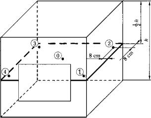
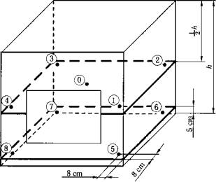
Before calibration, the effective working area shall be determined according to the operation manual of the temperature and humidity chamber or the user requirements.Multi-channel temperature and humidity measuring device is used to calibrate the temperature and humidity in the chamber. The temperature sensor and humidity sensor in the device adopt horizontal layered layout. The location from the side of the effective working area is 8 cm. The lower location is 5 cm above the bottom level of the effective working area, and the upper location is 20 cm below the top level of the
effective working area, as shown in Figure 1.
Temperature and humidity chamber with the effective working area height,h,less than 50 cm,
locate 5 points [see Figure la)
Temperature and humidity chamber with the effective working area height ,h, between 50 c m
and 100 c m, locate 9 points [see Figure lb)
Temperature and humidity chamber with the height of the effective working area,h,exceeding
100 cm, locate 13 points [see Figure lc)].

a) h <50 cm distribution plot

b) 50 cm ≤ h ≤100 cm distribution plot

c) h> 100 cm distribution plot
Figure 1 Schematic diagram of the sensor spot placement
For the temperature and humidity chamber with input cold mirror dew point probe in the working room, the distribution position of the sensor should be adjusted appropriately, so that the distance between the sensor in the upstream of the dew point probe and the air flow in the chamber is not less than 5 cm, and the distance between the sensor downstream of the dew point probe and the
dew point probe is not less than 20 cm.
For the temperature and humidity chamber with airflow blind area in the effective working area, a distribution point can be added in the blind area.
2. Temperature calibration
2. 1 Temperature calibration point
Temperature calibration points are generally 15 °C, 20 °C, and 30 °C, and other calibration points
can also be selected according to user requirements.During the calibration, the temperature shall be conducted in the order of low to high, and the temperature deviation at each calibration point shall be within ±0.5 °C (whichever is the center point temperature).If the humidity function is turned on, the humidity set value is generally about 60%RH.The calibration items are generally conducted under no-load conditions.
2. 2 Temperature calibration steps
After the temperature and humidity chamber reaches the specified stability time, the temperature of each point is recorded. The recording interval of the center point is 20s, and the recording interval of the other points is 2 min.Center points recorded 91 sets of data and other points recorded 16 sets of data.20s interval data use T ’i0 (i = 1,2, ??? ,91) indicates that 2 min interval data were used with Tnj (n=l, 2, ??? , 16; j =0,1, ??? , m-1), where m is the number of points, i and n represents the serial number of time (i time interval is 20s,n time interval is 2 min), j representing the serial number of point position.If the temperature and humidity in the chamber can be determined to be
balanced before the specified stability time, it can also be recorded in advance.
The temperature stability time shall be subject to the instructions, if not given in the instructions, the following principles: if the temperature change does not exceed 10 °C, the stability time from the temperature and humidity setting to the start recording data is 90 min; if the temperature change does not exceed 5 °C, the stability time is 60 min.The stabilization times of each calibration point are shown
in Table 1.
Table 1 Stability Time
 Headquarter Address :Tai'an High-tech Development Zone, Shandong Province
Telephon :+86 0538-5089056 +86 13605384645 +86 13953856217
Fax : +86 0538-5059718
After sale:+86 0538-5050959 +86 13605384645
Website : kqcgg.cn
E-mail : tadt17@dearto.cn / tadtzdh@dearto.cn
Copyright? Tai'an Detu Automation Instrument Co., Ltd. Lu ICP 14024757-1 